Configuration guidelines for On‑Demand services
Once your Lumen® NaaS Port is ready, you will need to prepare for On‑Demand services and configure your equipment using these guidelines.
Please read this guide carefully.
Prepare for On‑Demand services
Before adding On‑Demand services, complete the following steps:
- Work with property management or a vendor to extend the connection from the NaaS Port to your equipment. If you ordered a third‑party cross‑connect, verify installation has been completed.
- Connect your equipment to the extended connection or third‑party cross‑connect.
- Configure your hardware with the port settings in the NaaS Port ready notification email and ensure light levels are adequate (if applicable). Our policy is to hardcode speed and duplex on 1000BASE-T copper ports to 1000 full duplex.
- Verify the NaaS Port is active.
Customer provided equipment (CPE) and cabling
Router configurations
Verify your router is rated at the maximum speed of your purchased service. Non‑commercial routers (e.g., Linksys, Netgear) support only a few hundred Mbps maximum speed despite the interfaces supporting the GigE (1 Gbps) specification.
Ensure you have configured the following interface options (if available) on your router for the Ethernet port connected to Lumen:
- Interface speed: 1 Gbps (for 1 Gigabit interfaces), no auto‑negotiation
- Interface duplex: Full‑duplex, no auto‑negotiation
- Interface flow‑control: Disabled
- Interface keep‑alive: Disabled
For IP/data services only:
- Multi‑virtual circuit support: configure VLAN tagging traffic for converged services or multi‑VRF as needed.
- Traffic shaping: For CIRs below access rate (subrate), configure traffic shaping using an egress rate shaping policy on your router. Learn more about traffic shaping
Ethernet configuration guidelines
The following reference table provides basic Ethernet interface connectivity standards, cabling and compatibility. Customer edge (CE) device configuration guidance is provided for those Ethernet service speeds most commonly associated with performance issues.
| Interface | Media type handoff | Fiber mode | Bandwidth usage limit | Distance limit |
|---|---|---|---|---|
| 1000BASE-TX | Copper | N/A | 1 Gbps | 100m |
| 1000BASE-SX | Fiber | Multi‑mode | 1 Gbps | 220m–550m |
| 1000BASE-LX/LH | Fiber | Single‑mode | 1 Gbps | 10km |
| 10GBASE-SR | Fiber | Multi‑mode | 10 Gbps | 220m–550m |
| 10GBASE-LR | Fiber | Single‑mode | 10 Gbps | 10km/20km |
| 100GBASE-CWDM4 | Fiber | Single-mode | 100 Gbps | 2km |
| 100GBASE-LR4 | Fiber | Single‑mode | 100 Gbps | 10km |
Ethernet crossover cables (Switched services)
When connecting like devices (e.g., switch to switch), you may need to use an Ethernet crossover cable.
Learn more about Ethernet crossover cables
Basic configurations
The following configurations affect traffic. We recommend double‑checking the following items to ensure you don't encounter issues with On‑Demand services. Refer to your service activation notice email for technical parameters and information about your service.
- Verify power is correctly connected to your equipment by cycling it or turning it off and back on if this will not disrupt any other services.
- Confirm the physical port/SFP type (optical, electrical, OCn, ethernet) and cabling/fiber type (coax, single‑mode, multi‑mode) associated with the service type and adjacent equipment physical output are compatible.
- If applicable, verify optical bandwidth (1 Gbps, 10 Gbps, 100 Gbps) matches the adjacent Lumen equipment. Our policy is to hardcode speed and duplex on 1000BASE-T copper ports to 1000 full duplex.
- Unplug the cable and plug it back in to confirm it is installed correctly. If that does not provide resolution, the cable may need a straight‑through or crossover, or the fiber connection may need to be rolled.
- Verify that the distance of the cabling run is within specifications for CAT‑5/CAT‑6/CAT‑7/other fiber types related to the equipment transmit/receive parameters.
- If applicable, verify light levels being received and transmitted are within equipment specifications.
- Confirm the equipment interface's current state is ‘up’ or ‘in service.’
- Confirm that the interface settings match the Lumen configuration speed, duplex, and other port attributes, as applicable. If the port is an Ethernet port, ensure that auto‑negotiation is set to no or off.
- If applicable, and if you ordered service with another carrier between your equipment and our service, validate the local exchange carrier (LEC) loop/circuit is working as you requested. Confirm power to the LEC device and port connectivity. If there appears to be an issue with your LEC loop, engage and troubleshoot with the LEC before contacting chat support.
IP/data service configuration tips
Layer 2
- Verify VLAN ID. VLAN stacking (provider bridging) may have been configured depending on the service. Please verify that your VLAN ID matches the IP configuration email and the expected requirements. All On‑Demand services require VLAN tagging using the VLAN you selected, which is provided in your service activation email.
- For layer 2 point‑to‑point private services like Lumen® Ethernet On‑Demand, we forward based on the layer 2 MAC address. Bidirectional MAC address learning is required for the service to function between A and Z endpoints.
- Maximum Transmission Unit (MTU) requirements to pass standard IP traffic to the UNI is 1500. At layer 2 service must support 1522 for single tag. Any unfragmented IP traffic that requires IP payload higher than 1500 isn't currently supported.
- Verify that CoS profile matches the service activation notice and the expected requirements for Ethernet On‑Demand and Lumen® IP VPN On‑Demand; depending on the service type, the marking may be 802.1p, IPP, or DSCP.
- For cloud service providers with Ethernet On‑Demand and IP VPN On‑Demand, verify the service key, account information, and IP configuration provided in your service activation email. Contact your cloud service provider if you have determined your problem is not a Lumen service issue.
Layer 3
- Verify that IPv4 addressing (and IPv6 if applicable) matches the service activation email and the expected requirements. Lumen® Internet On‑Demand activations may include additional LAN block(s).
- MTU requirements to pass standard IP traffic to the UNI is 1500. Any unfragmented IP traffic that requires IP payload higher than 1500 isn't currently supported.
- Verify that static routes or dynamic routing protocol specifications match the service activation email and the expected requirements. Please note that protocols such as BGP may include additional details such as remote and local ASN, MD5, BFD, etc.
- For Internet On‑Demand activations, a routing registry object will translate to a list of allowed prefixes, as well as a combination of prefixes advertised by Lumen (full internet, internet + default, default only, Lumen customers only). On IP VPN On‑Demand, we announce the full VRF routing table and the default maximum is 10,000 unless specified otherwise by special requirements.
- Verify that CoS profile matches the service activation email and the expected requirements for Ethernet On‑Demand and IP VPN On‑Demand. Depending on the service type the marking may be either IPP, DSCP, or EXP (certain NNI offerings).
- For cloud service providers with Ethernet On‑Demand and IP VPN On‑Demand, verify the service key, account information, and IP configuration provided in your service activation email. Contact your cloud service provider if you have determined your problem is not a Lumen service issue.
Example VLAN configurations
All On‑Demand services use VLANs to separate services so that each has a broadcast domain. VLAN tagging separates services between the Lumen port and your CPE.
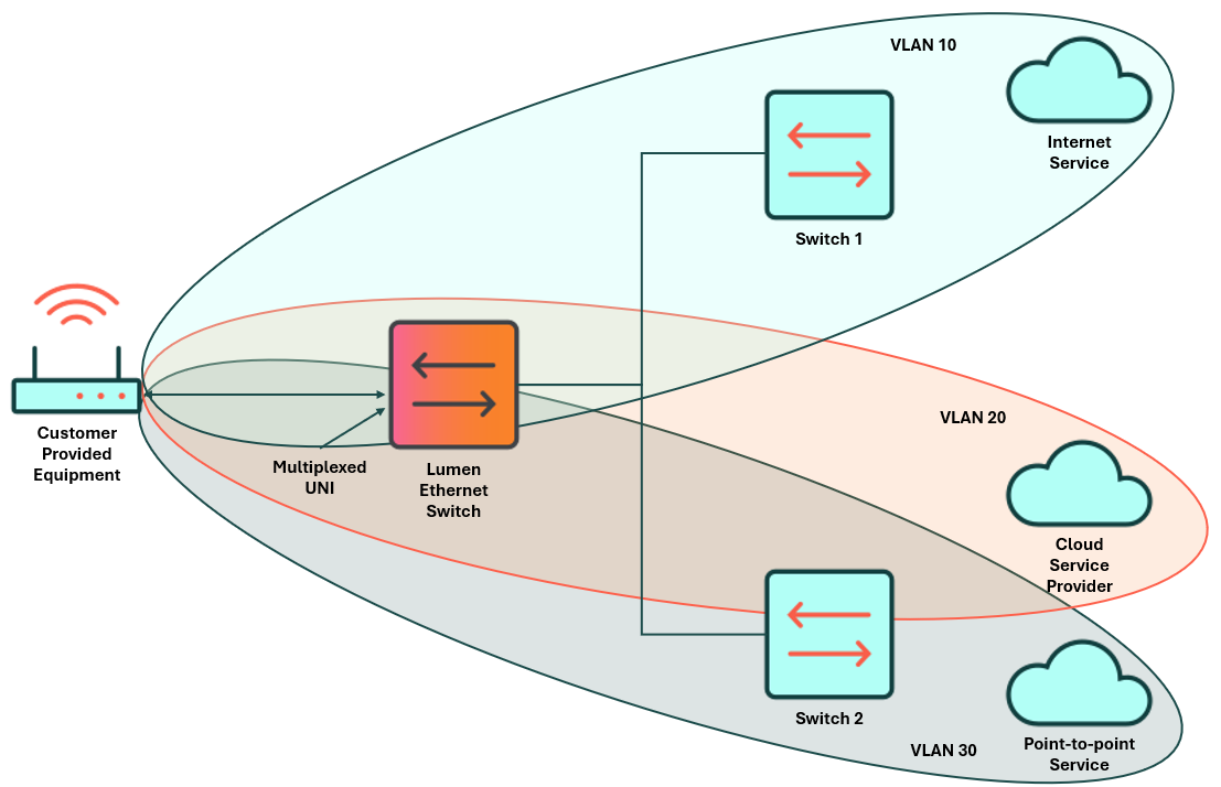
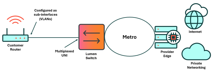
- A router port in Dallas is directly connected to the Lumen switch UNI. The configuration connects two Ethernet On‑Demand point‑to‑point spokes (St. Louis and Seattle) and one EVC for Internet On‑Demand.
Some services require double tagging to nest VLANs within other VLANs. The following examples will guide you in creating a VLAN with On‑Demand services.
Customer router example configuration for Cisco:
interface GigabitEthernet0/0/1
description Lumen UNI Dallas
!
interface GigabitEthernet0/0/1.101
description EoD EVC to Saint Louis (Spoke 1)
encapsulation dot1Q 101
ip address [WAN IP address determined by customer]
!
interface GigabitEthernet0/0/1.102
description EoD EVC to Seattle (Spoke 2)
encapsulation dot1q 102
ip address [WAN IP address determined by customer]
!
interface GigabitEthernet0/0/1.401
description EVC to Internet on Demand (IoD)
encapsulation dot1q 401
ip address [WAN IP address assigned by Lumen]
Spoke 1 example configuration for Cisco:
interface GigabitEthernet0/0/1
description Lumen UNI Saint Louis
!
interface GigabitEthernet0/0/1.101
description EVC to Dallas
encapsulation dot1Q 101
ip address [WAN IP address determined by customer]
Spoke 2 example configuration for Cisco:
interface GigabitEthernet0/0/1
description Lumen UNI Seattle
!
interface GigabitEthernet0/0/1.102
description EVC to Dallas
encapsulation dot1Q 102
ip address [WAN IP address determined by customer
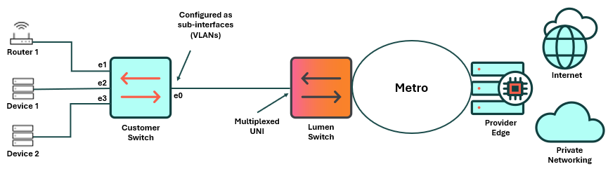
- A switchport in Dallas is directly connected to the Lumen switch UNI. The configuration connects two Ethernet On‑Demand point‑to‑point spokes (St. Louis and Seattle) and one EVC for Internet On‑Demand.
Customer switch example configuration for Cisco:
interface e0
switchport trunk allowed vlan 100,200
switchport trunk encapsulation dot1q
switchport mode trunk
interface e1
switchport access vlan 100
switchport mode access
interface e2
switchport access vlan 200
switchport mode access
interface e3
switchport access vlan 200
switchport mode access
Router 1 example configuration for Cisco:
interface GigabitEthernet0/0/1
description Lumen UNI Saint Louis
!
interface GigabitEthernet0/0/1.101
description Router to Switchport e1
ip address [WAN IP address assigned by Lumen]
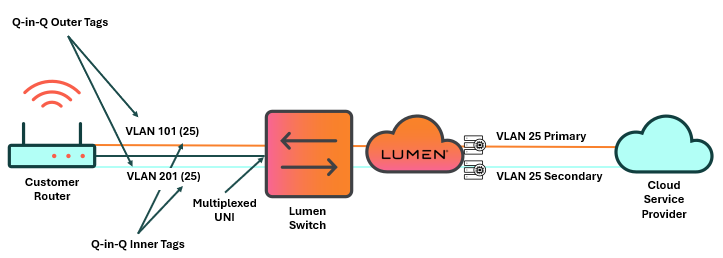
- A router port in Dallas is directly connected to the Lumen switch UNI. The configuration connects an Ethernet On‑Demand point‑to‑point service to a CSP that requires Q‑in‑Q configuration to terminate a single VLAN to the CSP using two distinct end‑to‑end paths. The egress must account for four extra bytes of overhead for double tagging. Therefore, the MTU on the port facing the UNI must be set to at least 1504.
Customer switch example configuration for Cisco:
interface GigabitEthernet0/1
description Lumen UNI Dallas – Primary
mtu 1504
!
Interface GigabitEthernet0/1.10125
encapsulation dot1Q 101 second‑dot1q 25
description “Cloud Connection Primary Peer”
Ip address 10.103.224.217 255.255.255.252
interface GigabitEthernet0/2
description Lumen UNI Dallas ‑ Secondary
!
Interface GigabitEthernet0/2.20125
encapsulation dot1Q 201 second‑dot1q 25
description “Cloud Connection Secondary Peer”
Ip address 10.103.224.221 255.255.255.252
- A router port in Dallas is directly connected to the Lumen switch UNI. The configuration connects an Ethernet On‑Demand point‑to‑point service to a CSP that requires Q‑in‑Q configuration to terminate a single VLAN to the CSP using two distinct end‑to‑end paths. The switchport facing the UNI must be a trunk that allows the VLANS to pass. The switchports that interface with the CSP must be configured to access VLAN so the outer tags can be placed in the frame. Q‑in‑Q on the outbound port must allow multiple secondary tags encapsulated in the outer tag. The egress must account for four extra bytes of overhead for double tagging. Therefore, the MTU on the port facing the UNI must be set to at least 1504.
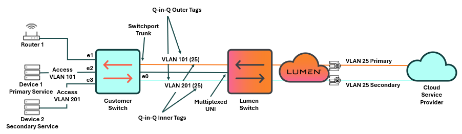
Customer switch example configuration for Cisco:
interface e0
switchport trunk allowed vlan 101,201
switchport trunk encapsulation dot1q
switchport mode trunk
mtu 1504
interface e2
switchport access vlan 101
switchport mode dot1q‑tunnel
interface e3
switchport access vlan 201
switchport mode dot1q‑tunnel
Device 1 example configuration for Cisco:
interface GigabitEthernet0/1
description Lumen UNI Dallas – Primary
Interface GigabitEthernet0/1.25
encapsulation dot1Q 25
description “Cloud Connection Primary Peer”
ip address [WAN IP address determined by customer/CSP
Device 2 example configuration for Cisco:
interface GigabitEthernet0/2
description Lumen UNI Dallas – Secondary
Interface GigabitEthernet0/2.25
encapsulation dot1Q 25
description “Cloud Connection Secondary Peer”
ip address [WAN IP address determined by customer/CSP]
Alternate Option to run the switch as trunks and perform Q‑in‑Q on a layer 3 device connected to the switch:
interface e0
switchport trunk allowed vlan 101,201
switchport trunk encapsulation dot1q
switchport mode trunk
mtu 1504
interface e1
switchport trunk allowed vlan 101,201
switchport trunk encapsulation dot1q
switchport mode trunk
mtu 1504
Router 1 example configuration for Cisco:
interface GigabitEthernet0/1
description Router to Switchport e1
mtu 1504
Interface GigabitEthernet0/1.10125
encapsulation dot1Q 101 second‑dot1q 25
description “Cloud Connection Primary Peer”
Ip address 10.103.224.217 255.255.255.252
Interface GigabitEthernet0/1.20125
encapsulation dot1Q 201 second‑dot1q 25
description “Cloud Connection Secondary Peer”
Ip address 10.103.224.221 255.255.255.252
Traffic shaping
- To ensure maximum throughput efficiency, enable traffic shaping on your equipment (CPE) switch or router.
- Traffic shaping is required to ensure that packets are not dropped when entering the network as traffic policing is applied on the Lumen network.
- If shaping is not enabled, Lumen (or one of our third‑party access vendors) will randomly drop traffic if your signal exceeds the committed information rate (CIR) that is contracted for the connection.
- Most enterprise‑class routers on the market should support traffic shaping.
- Lumen Ethernet services can scale from 10 Mbps to 30 Gbps as long as you can shape your traffic. If you are unable to shape your traffic, you should purchase service at the 1 Gbps speed tier to achieve maximum bandwidth utilization. Failure to comply with this recommendation will result in reduced throughput and performance.
- Example traffic‑shaping configuration parameters:
- Purchased service = 50 Mbps CDR
- Customer router = Cisco 2900
- Configure port level traffic shaper to 50 Mbps
Resulting example configuration:
! Match any traffic with class‑map:
class‑map match‑all class‑cpe‑wan‑out
match any
! Parent policy‑map matches class‑map traffic and applies shaper
policy‑map policy‑cpe‑wan‑out
class class‑cpe‑wan‑out
shape average 50000000
!
! Apply policy‑map outbound on Lumen‑facing interface:
interface GigabitEthernet0/2
service‑policy output policy‑cpe‑wan‑out
Ethernet service performance
The following variables impact actual throughput in a network during data transfer and testing:
- Bandwidth of the circuit
- Roundtrip latency from the sending host to the receiving host: Latency measures how long a packet takes to transit the network. Fiber propagation and electronics in the path can delay arrival, and protocol handshakes can affect TCP throughput.
- Packet loss during the data transfer: Packet loss is the loss of any frame or packet in the data flow and directly impacts Ethernet throughput—particularly TCP‑based application throughput. The loss of a single packet in a TCP flow will result in the re‑transmission of data and impact the TCP window negotiation process.
- Frame size: Generally, throughput efficiency improves with packet size as long as the configured maximum transmission unit (MTU) and maximum receive unit (MRU) support larger packets. Small packet sizes negatively impact throughput efficiency.
- TCP window size: Transmission control protocol (TCP) relies on a handshake dialogue, positive confirmation of data sent and received, and re‑transmission capability to recover lost data. TCP is most efficient when the protocol can negotiate a congestion window size and maintain that state for the duration of the data transfer session. Packet loss during the negotiation process will cause re‑transmission of data, disrupt the negotiation process, and impact the ability to reach full throughput.
Commonly overlooked configurations
Configurations required to successfully use On-Demand services that are often overlooked:
- Verify the VLAN ID you selected, which is provided in the service activation email, and use it to configure your router.
- NaaS Port speeds are hard-coded and set as duplex.
- Turn auto-negotiate off.
- Static routing is the default. BGP routing is optional and requires using the Internet Routing Registry (IRR).
Additional technical support
For additional support configuring or troubleshooting your network services, review our expanded index of technical topics:
On‑Demand support
- For issues with On‑Demand services, click chat in the lower‑right corner (within Lumen Connect).


